FG40
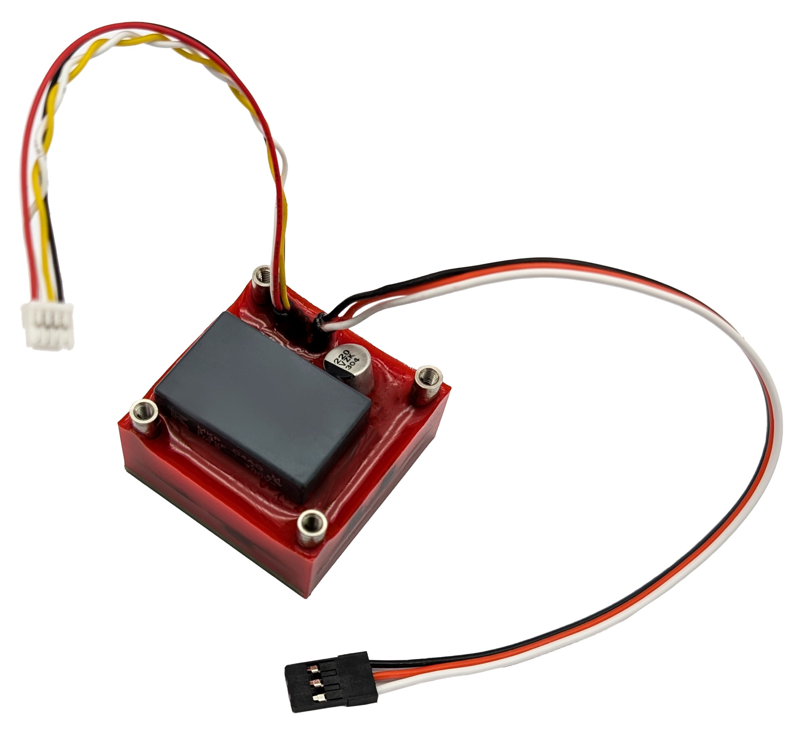
FG40 is a family of fully integrated solid-state electropermanent magnets optimized for applications where low mass, reliability, and resilience against vibration and environmental adversities are critical. FG40 contains a remagnetizable magnetic assembly and its controller in a single sealed package. With a wide supply voltage range and multiple communication interfaces, the device easily integrates into any end system. Certain features are available only in specific models.
Danger
High voltage. Do not attempt to disassemble or modify FG40 to avoid the risk of an electric shock.
Features:
25 kgf of holding force[1] in a 4x4x2 cm, 72 g package.
(De-)magnetization energy consumption of only 4 J.
Wide power supply voltage range of 4~30 V DC ensures easy integration into any end system.
Fully integrated solution with no external components required.
Highly robust and reliable:
Entirely solid-state construction, no moving parts inside.
Resilient against aggressive environments and vibration.
IP69 rated — dust-tight, waterproof.
AEC-Q grade 2 electronics.
Compatible with industry-standard interfaces, including:
CAN FD control with telemetry;
RC PWM and voltage level control input (select models only);
analog voltage status feedback (select models only).
Applications:
Magnetic locks, clamps, and holders.
Payload attachment in vehicles, drones, and robots.
End-of-arm tooling (EOAT).
Steel surface climbing legged robots.
Models and ordering codes
Modifications that are not explicitly listed may be available upon request. Contact Zubax Robotics for details.
Model name |
CAN interface |
Analog interface |
|---|---|---|
FG401M |
x1 UCANPHY Micro |
no |
FG401MA |
x1 UCANPHY Micro |
yes |
FG402M |
x2 UCANPHY Micro |
no |
Interface and power supply
Commands and telemetry are exchanged with the device via Cyphal/CAN FD and (in some models) via the analog interface.
The device is powered either via the Cyphal network ports or via the analog port connector. The built-in voltage regulator accepts a wide range of power supply voltages which allow easy integration of the magnet into the end application without the need for additional power converters. If the supply voltage exceeds the operating limits specified in this section, the device may continue operating but will reject magnetization commands until the voltage returns within limits.
When the device is operating near the minimum supply voltage with a high-impedance power source, an attempt to (de-)magnetize may fail due to the voltage drop caused by an increased current consumption. The device will refuse to perform a state transition until the supply voltage is restored to the nominal level. If the power supply voltage is not restored in a reasonable time since the arrival of the state transition command, the device may enter the fault state.
The magnet poles and mounting standoffs connect to the power supply ground through a high-impedance parallel RC network, preventing static charge accumulation. The RC network may cause negligible AC leakage currents to flow through the payload and mounting standoffs, which is normal and does not affect the device’s operation.
Parameter |
Note |
Min |
Typ |
Max |
Unit |
|---|---|---|---|---|---|
Supply voltage |
4 |
30 |
V |
||
Idle power consumption |
magnet not switching |
50 |
mW |
||
Switching current consumption |
CC mode, any voltage |
1 |
A |
||
Magnetization energy consumption |
approximate |
4 |
J |
CAN FD interface characteristics
The product supports the CAN FD bus interface, which may be doubly-redundant depending on the model. The primary interface is labeled CAN0 and the redundant, if available, is labeled CAN1.
Each CAN connector is equipped with an anti-backfeed diode to prevent the bus from sinking current from the device. This is particularly important in the event of a power short-circuit fault on one of the attached CAN buses.
The CAN FD interfaces may be equipped with different connector types upon request.
Parameter |
Condition |
Min |
Typ |
Max |
Unit |
|---|---|---|---|---|---|
Differential output voltage, dominant |
\(60 \Omega\) load |
+1.5 |
+5.1 |
V |
|
Differential output voltage, recessive |
\(60 \Omega\) load |
-0.1 |
0 |
+0.1 |
V |
Differential receiver threshold voltage |
0.4 |
1.15 |
V |
||
Differential receiver hysteresis voltage |
0.05 |
0.3 |
V |
||
Arbitration phase bit rate |
10 |
1000 |
kbps |
||
Data phase bit rate |
10 |
4000 |
kbps |
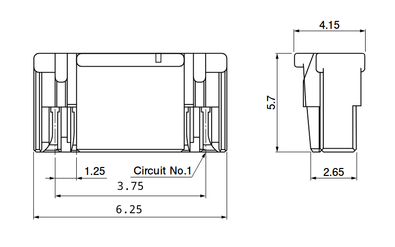
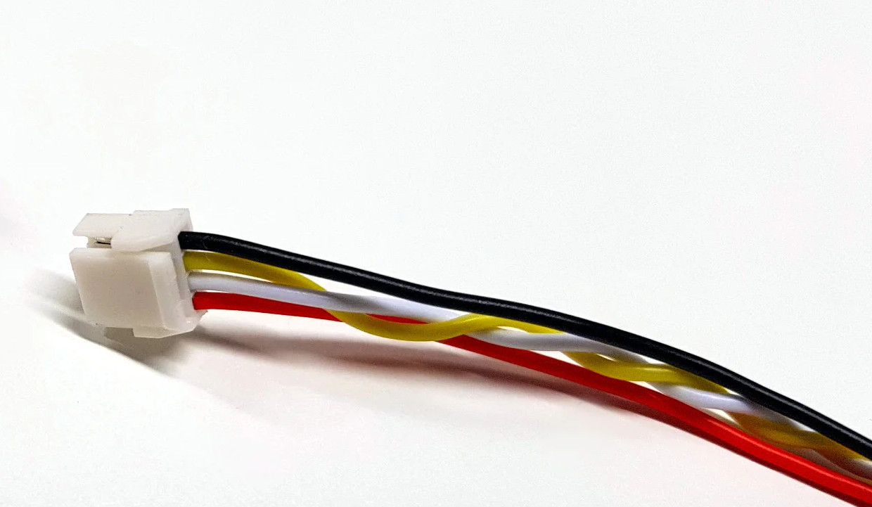
UCANPHY Micro connector
The UCANPHY Micro connector is specified in the UCANPHY Specification. This connector type is based on JST GH and is crimped on a cable; an external T-connector or a hub/splitter may be necessary to attach the device to the CAN bus. Suitable CAN bus hubs/splitters are available from Zubax Robotics; for example, see the 5-port CAN bus splitter.
Pin |
Type |
Function |
|---|---|---|
1 |
Power |
Power supply input |
2 |
Input/output |
CAN high |
3 |
Input/output |
CAN low |
4 |
Ground |
Ground |
Analog interface characteristics
The analog interface is implemented on a wire terminated with the industry-standard 2.54 mm three-pin RC PWM connector. Additional connector options are available upon request.
Symbol |
Parameter |
Min |
Typ |
Max |
Unit |
|---|---|---|---|---|---|
Logic input low |
1.0 |
V |
|||
Logic input high |
3.5 |
V |
|||
\(R_\text{pull}\) |
Pull resistance |
4800 |
5100 |
6000 |
\(\Omega\) |
\(V_\text{hi}\) |
High-level pull voltage |
3.3 |
V |
\(\newcommand{\colorpatch}[1]{{\color{#1}\rule{3mm}{3mm}}}\)
Pin |
Type |
Function |
|---|---|---|
1 \(\colorpatch{yellow}/\colorpatch{orange}/\colorpatch{white}\) |
Input |
Analog input with pull resistor feedback |
2 \(\colorpatch{red}\) |
Power |
Power supply input |
3 \(\colorpatch{brown}/\colorpatch{black}\) |
Ground |
Ground |
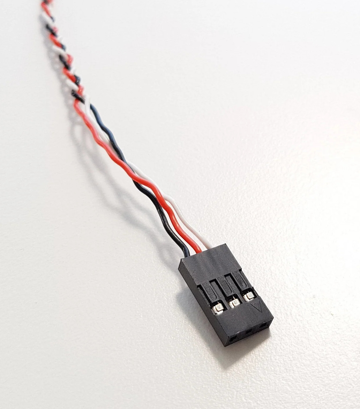
Analog interface cable with the industry-standard RC PWM connector
Absolute maximum ratings
The device is designed to be able to withstand the conditions specified in this section, but it is not guaranteed to operate correctly under these conditions. Exceeding the specified limits may cause permanent damage to the device.
Parameter |
Min |
Max |
Unit |
|---|---|---|---|
Supply voltage |
-0.3 |
+35 |
V |
Temperature, ambient |
-40 |
°C |
|
Temperature, internal |
+73 |
°C |
|
Analog port input voltage |
-0.3 |
+7 |
V |
CAN FD H/L input voltage |
-24 |
+24 |
V |
Mechanical stress, any direction, magnitude of |
250 |
N |
The maximum internal temperature is limited by the heat deflection temperature of the polymer composite body of the device, while the electronics is designed to withstand 105°C continuously. Modifications with a wider operating temperature range are available upon request.
Mechanical characteristics
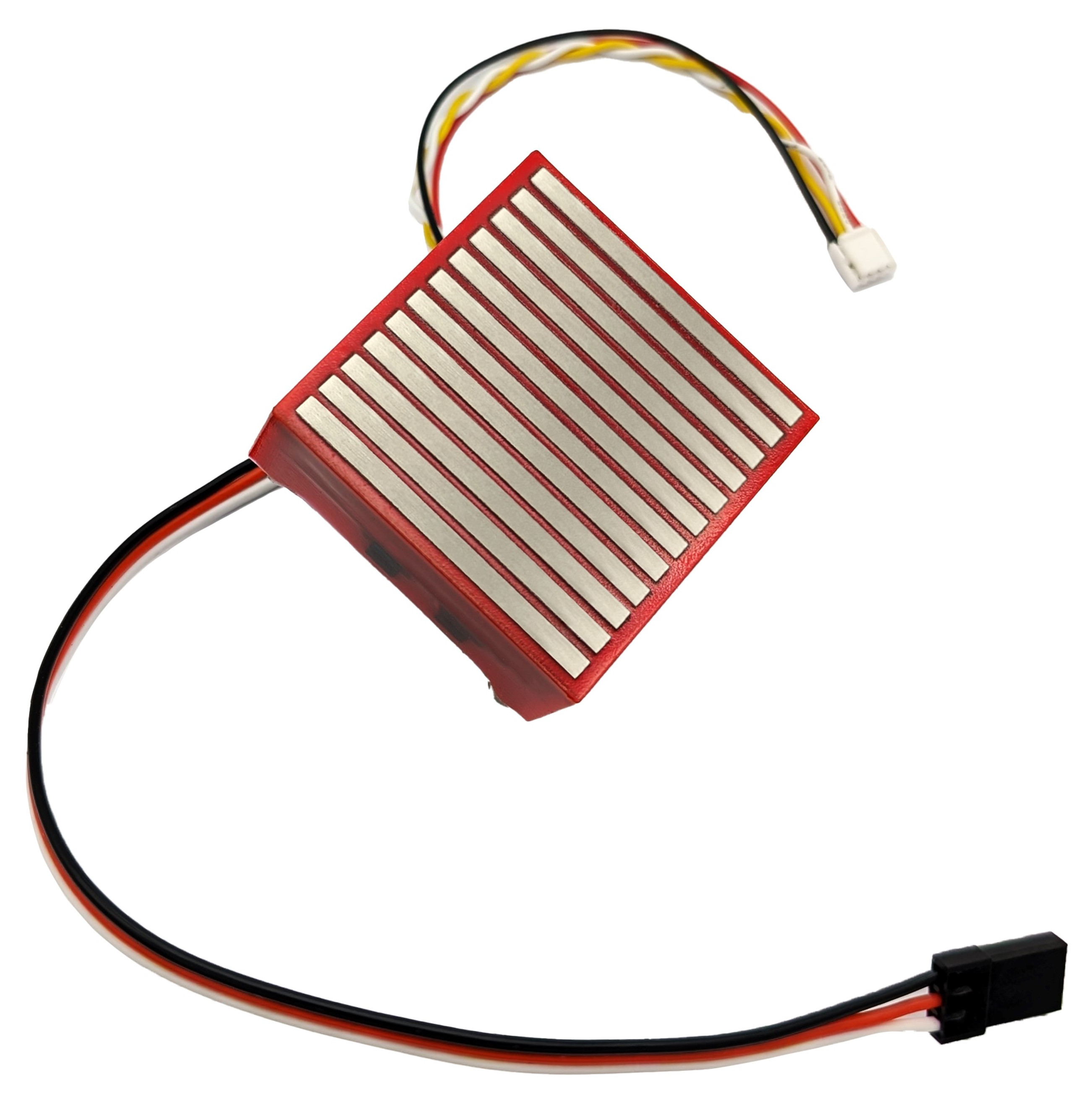
The body of the device is manufactured from a mechanically and chemically resilient polymer composite. The device is watertight (operable when submerged), dust-tight, and highly resilient to vibration and adverse chemicals.
The power supply and interface connectors are installed on cables exposed via the top surface of the device. The cables are terminated with connectors documented in the respective sections.
Parameter |
Value |
Unit |
|---|---|---|
Mass |
72 |
g |
Ingress protection |
IP69 |
|
CAN interface cable length |
12 |
cm |
Analog interface cable length |
16 |
cm |
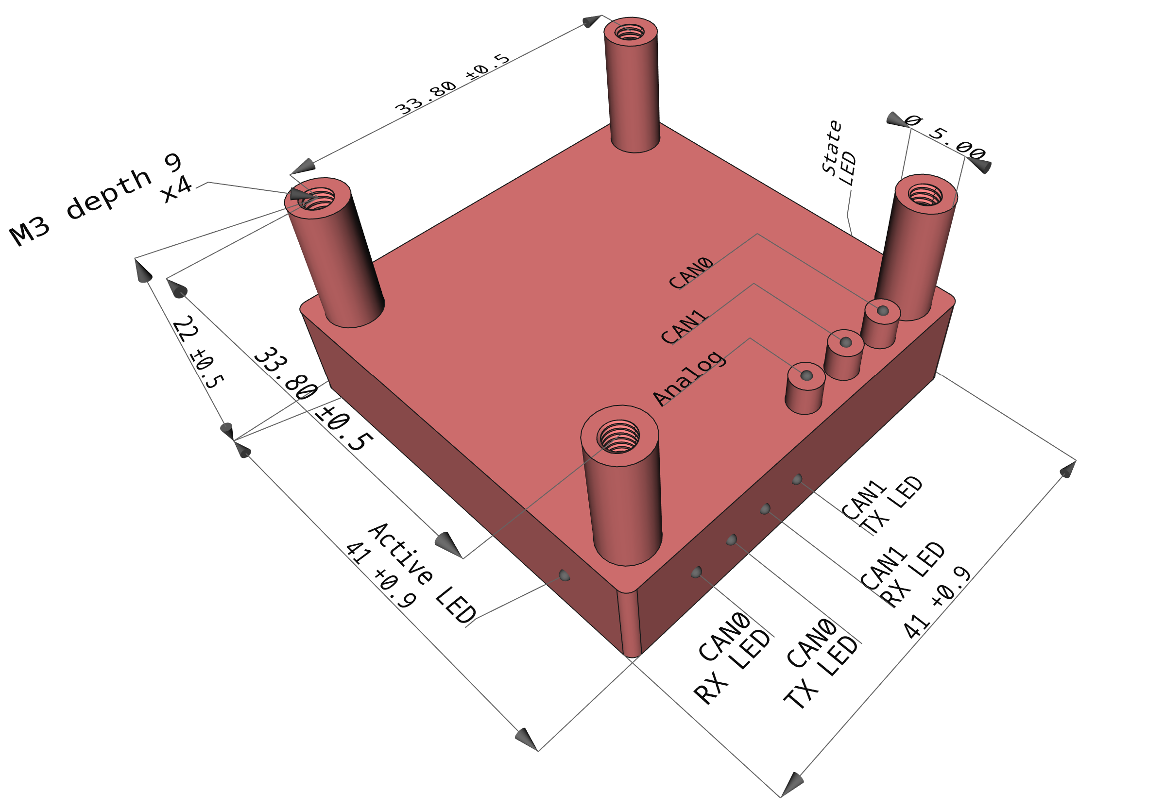
FG40 mechanical drawing and position of the key features. All dimensions are in millimeters. Interface cables not shown. Some interfaces are only available in specific models.
Magnetic characteristics
The holding force is measured against a 4 mm thick polished iron sheet in full contact with the magnet poles, with the force applied against the geometric center of the magnet perpendicular to the sheet surface. Lower magnetic permeability, magnetic saturation, or imperfect contact will reduce the holding force. Force applied with an offset relative to the geometric center of the magnet will also reduce the holding force.
Parameter |
Value |
Unit |
|---|---|---|
Holding force |
250 |
N |
The holding force decreases rapidly as the air gap between the magnet poles and the ferromagnetic surface increases.

Normalized holding force as a function of the air gap between the magnet poles and an iron sheet.
Reliability and functional safety
The device is built with AEC-Q grade 2 qualified electronic components. See chapter Reliability and functional safety for further information.
FG40 has not been found to cause adverse effects on sensitive navigation equipment under typical conditions, including magnetic heading compasses. For a detailed report, refer to On the interference of FluxGrip with navigation equipment.
Parameter |
Value |
Unit |
|---|---|---|
Replacement life |
8 |
year |
Operational service life |
50000 |
hour |
Magnetization cycle limit |
on request |
cycles |
Mean time to failure (MTTF) |
on request |
hour |
Compliance documents: